
PORT RUNNER
SUPPRESSION SYSTEM (PRSS)
The Port Runner Suppression System (PRSS) provides positive and effective traffic control at U.S. Border Lands Ports of Entry (LPOE). A port runner is a vehicle 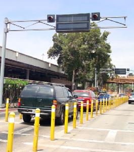 that tries to evade apprehension by forcing itself through the port without inspection. The PRSS has been successfully installed at LPOE vehicle border crossings. The system is organized in modular form and can be applied to any border crossings needing the same vehicular traffic controls.
The PRSS is a modular computer-controlled traffic control system that can be configured to control any number of traffic lanes. Traffic control is progressive so that when an incident occurs the traffic passing through the port at that time is safely and quickly stopped. The PRSS deterrent features serve to reduce and eliminate the number of vehicles that may try to breach the port for any reason while providing safe passage to regular travelers.
The typical PRSS operation is as follows:
1. PRSS activation is normally generated by a Customs Inspector who encounters a vehicle trying to evade inspection. The Customs Inspector activates the system by pressing any alarm button at the inspection station. A strobe light located on the inspector booth identifies the PRSS alarm origin.
2. Each port traffic lane is normally configured with the PRSS stopping system. Each traffic lane includes a zoned stopping system as follows:
![]() a. When a vehicle leaves the border customs inspection station, the vehicle enters stopping zone 1. Stopping zone 1 includes PRSS-controlled signal lights and message signs that provide warning messages in multiple languages.
a. When a vehicle leaves the border customs inspection station, the vehicle enters stopping zone 1. Stopping zone 1 includes PRSS-controlled signal lights and message signs that provide warning messages in multiple languages.
![]() b. Stopping zone 2 begins with mechanical lane separation barriers confining a vehicle’s travel to that lane. Speed bumps are located to slow traffic in this zone. Stopping zone 2 ends with a PRSS-controlled gate arm, traffic lights and overhead message sign with flashing emergency lamps. The stopping zone 2 equipment will cause all normal vehicles to halt travel.
b. Stopping zone 2 begins with mechanical lane separation barriers confining a vehicle’s travel to that lane. Speed bumps are located to slow traffic in this zone. Stopping zone 2 ends with a PRSS-controlled gate arm, traffic lights and overhead message sign with flashing emergency lamps. The stopping zone 2 equipment will cause all normal vehicles to halt travel.
![]() c. Stopping zone 3 ends with a PRSS-controlled tire shredder, gate arm, traffic lights and overhead message sign with flashing emergency lamps. The equipment in this stopping zone will cause vehicle tire damage designed to physically halt vehicle travel and allow apprehension.
c. Stopping zone 3 ends with a PRSS-controlled tire shredder, gate arm, traffic lights and overhead message sign with flashing emergency lamps. The equipment in this stopping zone will cause vehicle tire damage designed to physically halt vehicle travel and allow apprehension.
3. PRSS operation is monitored at the central control point usually located in the main security center or Head House. The central control point provides visual indications of all PRSS operations, including individual control of each exit lane individually. Test programs and alarm logging is accessible at the central control point.![]()
PRSS Control Components
The PRSS is modular, meaning that the control system and field-mounted traffic control equipment can be configured to the traffic stopping requirements of any facility. The components are:
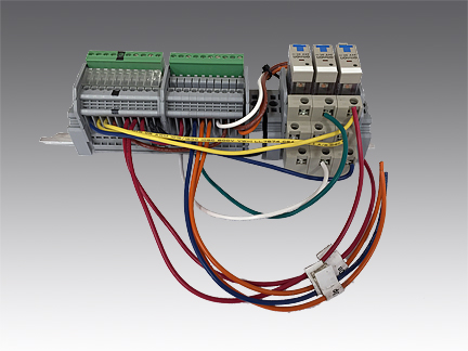
1. Control Module. The control module, PX-150-CM, includes the central controller and the interface components for interconnection to the field-mounted traffic control devices.
2. Remote Module. The remote module, PX-150-RM, accepts alarm inputs when the control module is located any great distance from the alarm input.
3. Operator Console. The operator console, PX-150-OC, is the human interface for the officers in the security control room.
4. Customs Inspector’s Booth System. Each customs inspection booth includes a system of alarm button(s) and strobe lamp(s) that (1) allows the officer to report and an alarm and then (2) directs all other officers to the location of that alarm.
5. PRSS Software System. The software system, PX-150-SS, provides the application software system.![]()
PRSS Traffic Control Components
The PRSS Traffic Control System is connected to traffic control equipment that ultimately communicates with vehicle drivers and provides stopping indicators, including one or more barriers to vehicular travel. Typical traffic control components are:
1. Traffic Signals. Traffic signals are used in each traffic lane and at the end of each PRSS stopping zone.
2. Changeable Message Signs. Changeable message signs are capable of displaying any alphanumeric message as either traveler information or notification that a Port Runner emergency condition exists.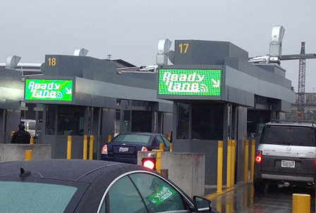
3. Extinguishable Message Signs. Extinguishable messages signs provide emergency messages whenever the PRSS is activated.
4. Auto-Gate Arms. Auto-gate arms are remotely controlled gate arms that can be lowered across the lane to stop traffic.
5. Tire Shredders. Tire shredders are sharp steel teeth that, when activated, deploy the teeth upward to cut through any tires that try to cross.
6. Retractable Bollard Systems. Retractable bollards are heavy duty round metal barrier posts that are stored in the ground and deployed upward when a barrier is required.
7. Cameras. The PRSS usually includes a closed circuit video system positioned to view activities in the exit lanes and at any other gates that are part of the PRSS.
8. Public Address System. The PRSS usually includes a public address audio system that provides alarm announcements to all responding officers.
9. Force Protection. Critical equipment and lane control is protected by crash rated bollards and barriers.
10. Signage. Signage is provided within each exit lane and in conjunction with the gate operators and tire shredders to indicate that caution is needed because severe tire damage can occur.![]()
PRSS Engineering Services
Priax Corporation can provide engineering services in support of the PRSS design, budgetary pricing, plans and specifications, equipment procurement, installation, warranty and maintenance. Priax Corporation is a GSA contractor, and the PRSS engineering support services are available on a current GSA contract. Please contact Priax Corporation for more information.
PRSS SATELLITE
CONTROLLER
Priax developed the Satellite Controller work in conjunction with the Port Runner Suppression System (PRSS), for those applications when an independent security subsystem is required that must interface with the PRSS facility-wide network. The Satellite Controller functions as a programmable logic controller (PLC) with special 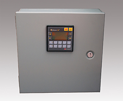 system interfaces, inputs, and outputs designed to match the specific requirements of the many different types of gate operators, turnstiles, wedge barriers, and retractable bollards available today in the perimeter security industry.
Field devices can be grouped and controlled by one Satellite Controller that will provide the local programmed responses and communicate with the PRSS network controller located elsewhere in the facility.
Each PRSS Satellite Controller is a standalone device that can operate independently with no instruction from the network. In case of network failure, the Satellite Controller will continue to operate unaffected, carrying out the preprogrammed instruction set. In case of a power failure with no battery backup, the Satellite Controller is designed to reactivate and continue normal operations when power is restored. Battery backup can also be provided.
COMBI-POLE
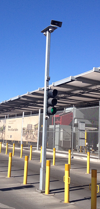 The Priax Combi-Pole, or Combination Equipment Mounting Pole, provides a simplified and cost effective mounting for much of the equipment required in a typical Port Runner Suppression System (PRSS) alarm zone. Normally, a PRSS alarm zone is located along the typical flow of traffic and includes traffic signals, alarm strobe lights, audible alarm equipment and surveillance cameras. The Combi-Pole is designed to accommodate this equipment on one pole enabling ease of installation and future maintenance.
Rugged welded construction and 100% galvanized plating ensures long life under all weather conditions. Heavy duty mounting base and 8 point mounting ensures that this pole will remain standing in hurricane force winds.
A typical installation includes:
- 3-lamp traffic signal, red/yellow/green including solid state LED lamps with rotatable base
- Flashing red alarm warning strobe activated during alarm conditions
- High power all weather audible warning loudspeaker for warning tones and audible messages
- Surveillance cameras, dome style, one or several, for roadway and area surveillance/recording
The Combi-Pole includes a customizable top mounted section that can be adapted for special equipment mounting. The Combi-Pole can also include the PRSS zone control system with enclosure.
REMOTE CONTROL
INTERFACE (RCI)
Priax developed the low voltage remote control interface board (RCI) to provide low voltage remote control of remote high voltage functions. In particular, high voltage traffic signals can be controlled with low voltages, providing higher safety and reliability. Since all new traffic signals are using LED lamps today, it seems reasonable all future control should also be low voltage.
The interface board can control voltages to 600VAC and currents to 1.2 Amperes. The control inputs are photo-optically isolated from the high voltage circuits providing full protection to the low voltage circuits. Zero crossing switching is utilized to minimize high voltage switching noise that could affect other equipment.
Each interface board can control up to three high voltage functions. Each of the three functions are completely independent and can be operated in any combination, intermittently or continuously without board heating or failure.
The interface board occupies less than 9 square inches including room for removable connections for all line, load and control cables. Board mounted LED diagnostic lamps indicate the signal conditions of each function. Each interface board is provided with a mounting clip for easy mounting in equipment enclosures, such as traffic lights. The mounting clip can be installed during equipment enclosure production and the circuit board installed later after the equipment is installed on site and ready for wiring connection. Each interface board has been conformally coated with a special compound to resist high humidity and condensed liquids.
BARRIER REMOTE CONTROL
INTERFACE (BCI)
Priax developed the barrier remote control interface board (BCI) to provide low voltage remote control of all types of remotely located tire shredder and barrier gate devices. In particular, all types of tire shredder and barrier gate systems located from feet to miles away can be controlled with low voltages, providing higher safety and reliability.
 This interface board can control voltages up to 600VAC and currents to 10 Amperes. The number of control circuits can be 1 to 8. Additional circuits can be provided as an option. The control inputs are isolated from the high voltage circuits, providing full protection to the low voltage circuits and main computer system.
Each interface board can control up to 8 high voltage functions. Each of the 8 functions are completely independent and can be operated in any combination, intermittently or continuously without heating or failure.
The interface board includes built-in test and diagnostic functions, allowing a service technician rapid problem diagnosis and test operation of all connected barrier devices. The built-in testing functions allow in-field operation of all connected equipment for troubleshooting purposes without the need for operating the equipment from the central control point.
The interface board is very compact with a DIN rail mounting system, allowing easy integration into all types of remote tire shredder and barrier gate systems. Removable connections for all line, load and control cables are included. Diagnostic lamps indicate the signal conditions of each function. Each interface board is provided with a DIN rail for easy mounting in equipment enclosures. The DIN rail mount can be installed during equipment enclosure production and the circuit board installed later after the equipment is installed on site and ready for wiring connection.
CROSS BORDER WIRELESS
ALARM SYSTEMS
The Land Ports-of-Entry (LPOE) Alarm Notification System provides alarm communications between officers on both sides of the U.S.-Mexico border. The alarm system provides additional time for the officers to react when there is an emergency situation. The first 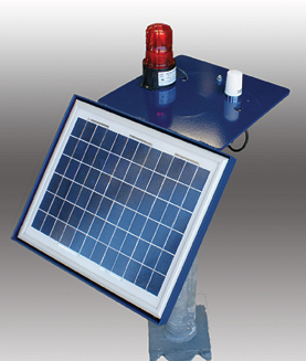 officer, on either side of the border, seeing an emergency will press the alarm button. The alarm is immediately communicated to all other alarm stations in the form of a loud siren and a flashing strobe light. Each alarm automatically continues for one minute (programmable) unless the officer presses the reset button.
Each alarm station is self-contained with a wireless connection to other alarm stations. Up to 16 alarm stations are possible in each mesh network with all stations communicating the alarm information. Each alarm station includes a battery and a solar panel so no external power is needed. There are only two controls on each alarm station: an alarm button and a reset button.
- The alarm button is pressed to alarm that station and all
the other stations in the network for one minute unless reset - The reset button is pressed to reset the alarm condition.
The reset button is also used for system testing
All labeling and instructions are furnished in the language of the country where installed.
Network communications are provided by an encrypted spread spectrum high power radio system operating in the ISM radio frequency band, 902-928 MHz. Communications are full duplex meaning that the stations communicate back and forth to verify both alarm conditions and normal operations. Typical range is over 1 mile although the antenna configuration can be changed to extend range.
Power is provided by a sealed lead-acid battery with a solar panel to maintain battery charge. The conservative design will operate each alarm station for more than three weeks with no sunlight present.
A built-in testing system allows one side of the border system to test the system on the other side of the border without having to visit the station. Testing will separately test the local station and then the remote station by sending a test signal and analyzing the response. The response includes a test of the battery in the remote station. The test does not cause a system alarm.
![]()
![]()
 SELECT
CATAGORIES